thisismyrobot
Littered with robots and Python codeSMS reminders for Remember The Milk in Australia
To do this you will need one extra (but free) service - twitter . Now, the instructions:
-
Get yourself a twitter account if you don't already have one.
- Go to http://www.rememberthemilk.com/services/twitter/ and set up twitter direct messages for reminders.
- Then go to http://twitter.com/devices and set up your mobile - making sure you chose "Direct messages" under "Device updates".
Flattr integration
 above each post will allow you to contribute to
thisismyrobot
, something I will gratefully repay with lots more projects! :)
above each post will allow you to contribute to
thisismyrobot
, something I will gratefully repay with lots more projects! :)
Face detection with OpenCV 2.0 & Python 2.6
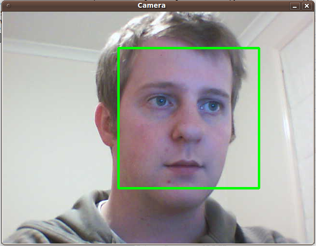
I've been wanting to play around with OpenCV under Python for ages and today I finally had the free time to have a go. Googling for some good tutorials lead me to a fantastic "hello world" script by Jo Vermeulen. The script used an OpenCV Python wrapper called CVtypes and was based on work done by Nirav Patel with an earlier version of OpenCV.
I wanted to work with the latest version of OpenCV and their new Python bindings so I decided to rework Jo's script for OpenCV 2.0. The results are above and the source code is available here: http://github.com/thisismyrobot/gnomecam/raw/master/face-detect.py
As a side note, I found the installation process for OpenCV under Ubuntu 9.10 utterly horrible. I eventually stumbled across this article that provided the correct steps to get it all working.
GPS Speedometer project

Inside the trendy "lunchbox" is a small GPS sensor and a PICAXE that work together to display the current speed in Kilometres-per-hour (KPH) on the display - forming a universal speedometer . In an attempt to make this project as simple as possible, the PICAXE uses PWM to output 0-200mV to a 0-200mV DC Voltmeter . This removes the need for a (more expensive) dedicated LCD as the circuit can be connected to any multimeter with a 200mV range setting.

The program reads in the KPH from the GPS unit ( one of these ) using the serial pin, multiplies that number by 4 and sets its PWM output to the result.
The PICAXE code is available here on GitHub.
The PWM output ranges from zero the supply voltage to the chip - in this case 5V. This is then limited to 0-3V by a Zener diode and further reduced to 0-200mV using a potentiometer wired as a voltage divider .
The result is an accurate speedometer that can be used in a car, boat, bicycle, motorcycle without any sort of special configuration and that costs virtually nothing. Performance-wise, it updates once every second and the speed is steady and accurate to within +/- KPH at highway speeds.
Pong game blue glowing coffee table prototype procrastination outlet

Well, this proves I still exist :)
After much effort I realised that I haven't been able to keep to any sort of regular uploading schedule so, to limit disappointment I will simply promise to post any cool projects that I work on when they happen - I recommend following my RSS feed (the big orange image to the right) to make this easier.
In three weeks I will have completed the last exam keeping me as an under graduate! Obviously, exams study requires dedicated procrastination which has lead to the pretty picture above.
I purchased a Velleman pong kit from ThinkGeek a week ago and set about testing out an idea - to make a coffee table with pong embedded (okay, I admit, not the most original idea...).
After constructing the kit I wired it up to the small in-car TV that I had laying around, added a piezoelectric speaker and a 4 gratuitously blue LEDs.
This works surprisingly well so the next step is to find a coffee table that I can wedge it into...
 In daylight
 The constructed pong kit, pre-modification
 Detail of the modifications.
Taking photos in the daylight helps...
 Click on it for a high-quality version.
The real google calculator
 Well, sort of...
Essentially, you are looking at the combination of a clunky old NS600 reverse polish notation calculator with a USB->RS232 adapter and a small chunk of Python brought together to create a cloud information display (think of it like a chumby , but far more ghetto...)
Using the python script, the calculator displays how many unread emails I have in my gmail account, and how many unread items are in my google reader list. The decimal point display (actually just a LED) splits the two, so the counter will show no more that 99 unread google reader items and no more than 9999 unread emails (this may seem the wrong way around, but I'll explain this later on). Using this logic, the (crummy, low-light) image above shows that I have 12 unread emails and 47 unread google reader items.
The logic of the python script is pretty simple:
- Get the current unread counts for gmail and google reader
-
Make sure the unread counts are less than there maximums
- Multiply the email count by 100 and add it to the google reader count
- Press the +/- keys (using relays) until the number displayed is correct
 The modifications
The mechanicals of the modification are also really simple. A pair of 5v DIP relays are directly triggered from the Request To Send (RTS) and Data Terminal Ready (DTR) pins. These two pins are directly controllable through the python
pyserial
library, using the setDTR() and setRTS() methods. The calculator was originally powered off a 9v battery, but the internal ic's work perfectly well off the 5v from the usb port.
The relay's are switched on for 0.1 seconds, and the delay between sequential "on's" is also 0.1 seconds - this was the fastest reliable speed. This means that the calculator can increment by 5 every second. This time is important because when a new email is received, it has to "press" the '+' key 100 times, which takes 20 seconds. That is why the emails are on the left of the "decimal point", and the unread google reader count is on the right, as I receive google reader items more often than I receive new emails.
Well, that's it. Of course I should attach the code to this post but, to be honest, it is a bit of a shambles. A reliable, working shambles, but not something that should be inflicted on other people. I will re-factor it properly, give the calculator a clean up, add some more technical detail, take some better photos and make a nice video for my next post.
If you are reading this and want more information before my next post, please don't hesitate to leave a comment.
Testing out the sonar sensor
Just a short video of the Maxbotix EZ0 sonar sensor hooked up to the helicopter. The code running on the Picaxe simply reduces the pulse-width to the servo by 20% if something is closer than 30cm. This is too close for actual use, but demonstrates the concept.
I was going to have a lot more to show from today, but 20 seconds after I finished filming this, the batteries in my rc controller went flat, the helicopter took on a mind of it's own, flipped over and proceeded to rip off the top rotor...
Installing the sonar range sensor

I moved the RC Receiver and Gyro electronics back to the position they were in when I bought the helicopter, and it has massively improved the flight stability, so I will stick with the layout that the designer's chose...
I can not wait to get cracking with the code now!