thisismyrobot

Littered with robots and Python code

Changes follow-up

I have now put through the majority of the changes I wanted. The new layout should be visually identical under FF2 & 7/8b. If it looks wonky under your browser, let me know in the comments.

Yes, I know IE6 looks a little strange, it is not centering the page background properly, will sort asap.

Changes

I have just pushed through some minor design alterations - more to come.

Keyboard IO Detail


Here is some further detail on the keyboard -> 4069 Inverter IC's. Within the grey border is a simulated circuit for a Caps/Num/Scroll lock LED circuit. The "switch" is controlled by the PC, using the Caps/Num/Scroll lock keys. When the switch is held LOW, the LED lights, and the inverter also switches on. When the switch is held HIGH, the LED turns off as their is no voltage difference between its (+) and (-) terminals and the inverter switches low.
The 100 Ohm Resistor is a guess, and there to stop the LED blowing. As described above, the circuit is just a simulation of what would be read with a multimeter across the pins of the LED.

In the final circuit (above), I removed the LED's, leaving their connection open-circuit, so essentially, the top of each of the diagrams can be ignored. This does not negatively effect the operation of the circuit.

Should have read this first...

I just found this article on GAL (Generic Array Logic) ICs. It would have been nice to have seen this before I started work on the Hex Inverter -> BCD-Decimal ICs in the motor controller system. I will have a go with these at some point and report on the results.

source

Hexapod gets an upgrade

The very cool Hexapod robot from Micromagic Systems has just received an upgrade - its very own router!
Hexapod's creator, Matt Denton has taken it to the next level with the design of a routing head attachment for the robot. Currently implemented as floating pen, the robot interprets DXF files into positional XYZ commands for the body of the robot. The body's position is controlled by 6 three-degrees-of-freedom legs, using an onboard processor - the p.Brain.
Hexapod's fluiditiy of motion really has to be seen to believed!

Hexapod videos:
Being put through its paces
Using the pen attachment.

source

A lot of hot-glue and some metal drumsticks

Let's make robots! has this incredibly funny robot amongst its robot projects. It is a little Picaxe-powered tracked rover that plays and samples a drum beat on whatever it finds. It will find an object ultrasonically and drum away at it using three drumsticks. It records this drumming, then replays the recording, adding its own fills on top.

Motor Controller Detail

Here is a closser view of the Motor Controller System.

The H-Bridge is from the Cybot from Real Robots.
The Battery is a Lithium Ion pack from my RC helicopter.
It supplies approx 7 volts to the H-Bridge. There is a feed of 7v and Gnd from the H-Bridge (the top two heatshrinked wires heading of the H-Bridge) that powers the IC's on the Logic board.
The keyboard controller has three wires going to the Logic board.
The grey ribbon cable takes the Logic boards outputs and sends them to the H-Bridge.

For anyone wondering why I have a PS2/USB board in there after my statement about saving USB ports, it is so I can test the robot on any laptop or PC without rebooting first.

Motor Driver Logic


Here is the basic circuit for the motor controller. As you can see, I have salvaged an old PS2 keyboard's IO board, connecting the negative pins of the LED's to the 4069's inverter inputs.
This is because the LEDs turn on when their negative leg is pulled to ground by the keyboard controller. The output of inverters goes to the inputs of a BCD -Decimal IC . This converts the binary number held in the LED's states to a discrete high-pin on the 4028's output.
This will give me the 6 discrete control states for the motor controller described before, as well as "all off" and an auxiliary .
In my 75% complete application, the Caps Lock LED controls the left motor, and the Num Lock LED controls the right motor.
The reason that I used the Caps/ Num /Scroll Lock LED's is that the Robot will not need text input whilst driving. I used a clunky old PS2 interface as the Microclient Jr only has 3 USB ports, and I did not want the power-hog of a USB Hub if I needed more that 2 extra peripherals.

current state


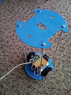
Here it is in its current state (click to enlarge).

The height extension was courtesy of 450mm lengths of hollow aluminium tube, with 5mm bolts tapped into the ends.

This is the 75% completed motor controller system. This will interface via the white (USB) lead to the mini PC. More info on the USB IO interface to follow (the purple plug should give it away).

All that is needed for completion is creation of the "high-level" motor control - currently the PC can only turn on or off the left or right motor. The goal is to have the PC output one of six discrete commands

-left-on-spot
-left-around-right-wheel
-forward
-reverse
-right-on-spot,
-right-around-left-wheel.

This will be accomplished with a mass of diodes heading into the H-Bridge :D

errata

And, just so as I don't stand out from the crowd, I will post the odd bit of robot-related news that grabs my attention :)